If you haven't seen the video for this project, consider watching it first! The rest of this post will make more sense after that.
It came to me in a dream. I was carrying a heavy metal box on the train through a long tunnel that looked like either Porter Square Station or perhaps the DC Metro. I recognized the box as something I'd seen at WardMapsWardMaps is a map and transit memorabilia store near Porter Square in Cambridge that is rather dangerous to the wallet of anyone like me. This indicator isn't even my largest or most unwieldy purchase from there; that dubious honor goes to the MBTA map plate I bought on my first visit. the previous day, despite its details shifting a bit every time I looked at it.

I did what any witch would do after receiving such a clear-cut dream: I bought it. I hoped for the rest of the week that it was still there on the shelf by the window at WardMaps until I finally had a chance to swing by again after the MIT Flea. When I made it there, it was gone from the shelf and I looked around and found it – in the arms of another customer. (If you're reading this, hi!) After a brief conversation with the store clerk, I learned that there were more of them in the basement and that they came out of red line trains.
I lugged it back to Porter to head back to Alewife and towards home, and it was just as heavy as I dreamed it'd be. I carried it in a shopping bag, scared that someone would recognize it as a train part and I’d get in trouble somehow, even though I knew in the back of my mind that people had carried weirder stuff on the T.
A brief introduction to not-quite-modern railway signaling
To understand what this device does, we have to dive into what “automatic train operation” (usually abbreviated ATO) is, and how it works – and to understand that, we first have to look at traditional railway signaling.
Railways have an interest in making sure their trains don’t crash into each other. To do this, they employ a signaling system, which has one major job: eliminate the potential of a collision by making sure trains can’t get close enough to each other at all. If you’ve ever been on a passenger train and seen a device that looks something like a traffic light, you’ve seen this system in actionSignals can take many other forms, including semaphore arms (common on lines that haven't been modernized) and lights mounted in a circular pattern (common on the Northeast Corridor).
Signal aspects
Lighted signal heads can convey more information than a typical traffic light, though, by displaying multiple colors of light at once, or by lighting lamps at different positions. Each combination of lamps is called a signal aspect. Aspects are commonly used to convey speed limit indications to train operators, in addition to the usual “stop, do not proceed” or “safe to proceed” indication.
Blocks and track circuits
To prevent trains from occupying the same area, tracks are typically divided into fixed blocks. When a train is occupying a block, it electrically connects the two rails it’s moving on, completing a “track circuit.”Track circuits must be designed to indicate the absence of a train with absolute certainty, since they are safety critical systems: if a signal indicates that it's safe to proceed when there is a train already occupying a block, that is, to use an industry term, Very Bad. In a way, it's more accurate to say that the signaling system can infer where trains are because it knows where they aren't. The signaling system is able to detect this, and sets aspects displayed on other signals appropriately (usually “stop” on the block the train is occupying and the one behind it, although this depends on track conditions).

(From Mangoe and Completefailure on Wikimedia Commons)
(Modern systems use communications-based train control to communicate the exact position and speed of trains to the signal system. CBTC systems create “moving blocks” around trains, which allows for safe operation with less margin of error, generally resulting in lower train headways than a fixed-block system. This isn’t relevant to this discussion, though – the MBTA still uses fixed blocks on all of its services.)
Collision avoidance and audio frequency track circuits
With a fixed-block system that just changes aspects on signal heads, there’s still potential for operator error. What if an operator falls asleep and misses a stop signal?
To solve this, we could somehow communicate to the train upon entering a block that there is a stop signal there, and install a device on the train that engages the brakes as appropriate.Older systems use mechanical devices to do this (“trip-stop”), but we’re more interested in electronic systems for reasons which will become obvious in the next section. Since this is a safety-critical system, we wouldn’t want to use e.g. radio to deliver such a message. What if we could send this information over the track circuit that the train is already using (to communicate that it’s occupying a block)?
This is exactly what audio frequency track circuits do. The signaling system doesn’t need to present a fixed voltage on the rails to determine whether or not a train is occupying the block – it can present a waveform containing information about signal aspects instead, which train equipment can read. They’re called “audio frequency track circuits” because the signals use frequencies in a range humans could hearOf course, under normal conditions, you couldn’t – but connect a speaker to the rails, and perhaps it'd be a different story..
In a simple collision avoidance systemalso referred to as “automatic train stop”, all we need is information about whether or not a stop signal is present, but we can do much more than that.
Automatic train control
The MBTA has lots of weird track speed limits right now, and even before those were put in place, there were sections of track that needed to be taken more slowly than others (e.g. tight curves). An operator going over these speed limits isn’t likely to cause a collision, but speeding can cause derailments, which tend to disrupt service and cause those pesky regulators from the Federal Transit Administration to show up.
By building off of collision avoidance equipment and audio frequency track circuits, we can prevent overspeeding. Signal aspects can already indicate speed limits to train operators. If we present these aspects along with the train’s current speed to the collision avoidance system, we can automatically apply brakes if the operator goes overspeed for more than a few seconds.
This protection system is called automatic train control (ATC for short).
Automatic train operation
At this point, the train already knows how fast it should be going (at least between stations). Why not just let it regulate its own speed, accelerating and decelerating as needed to respond to changing speed limits?
This is called automatic train operation (ATO for short), and the MBTA currently does exactly this on the Red and Orange lines. Operators still manually brake for stations and control the doors, but under normal conditions, the train regulates its own speed.
This is why (at least at the time of writing) riding in Red line trains going across the Charles River (and southbound Orange line trains between Sullivan and Community College, and other areas with very slow speed limits) feels exactly the same every time, with the same acceleration/deceleration pattern, regardless of who is operating the train.
Information on the MBTA’s usage of these systems on the public internet is sparse, but we were able to figure most of this out from a few sources:
- The MBTA operates (or at least has operated, in the past) multiple compatible AFTC systems (USDOT 1986 referencing the General Railway Signal system on the Braintree branch on pg6, and the Union Switch & Signal system on the Orange line).
- MBTA's 1976 Rules for Trainmen describes operation of the ATO system, including a device that sounds suspiciously like the one we have, in the “Rules and Procedures for Operating In-Cab Signal Territories of the Rail Lines”, starting on page 76.
- The MBTA designed the Braintree branch (then called the South Shore Extension) with in-cab signaling in mind. Annual reports from 1978 to 1984 discuss this and other in-cab signaling projects in more detail.
With all of that covered, we are finally ready to start breaking down what this device does.
What is this thing?
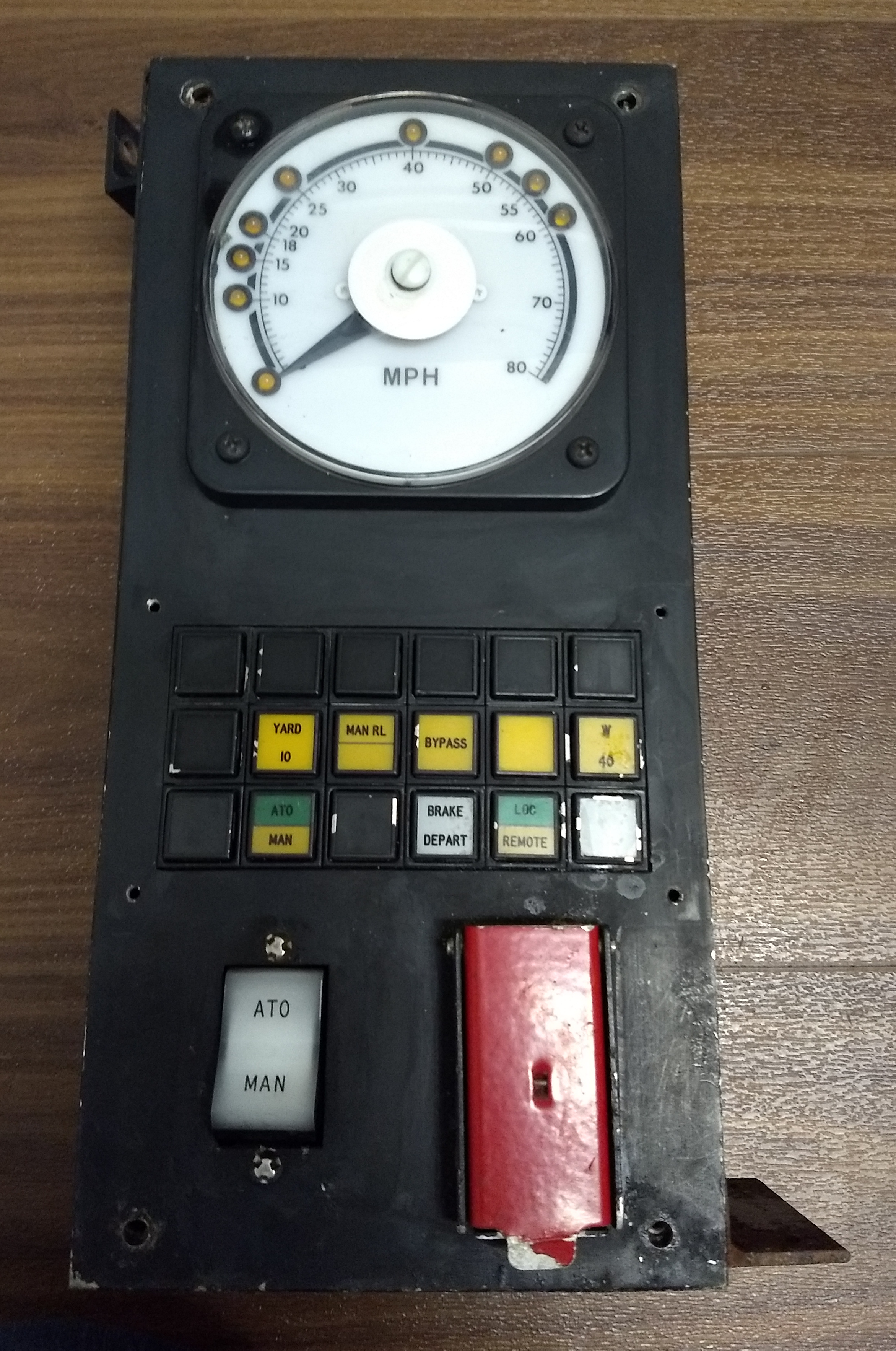
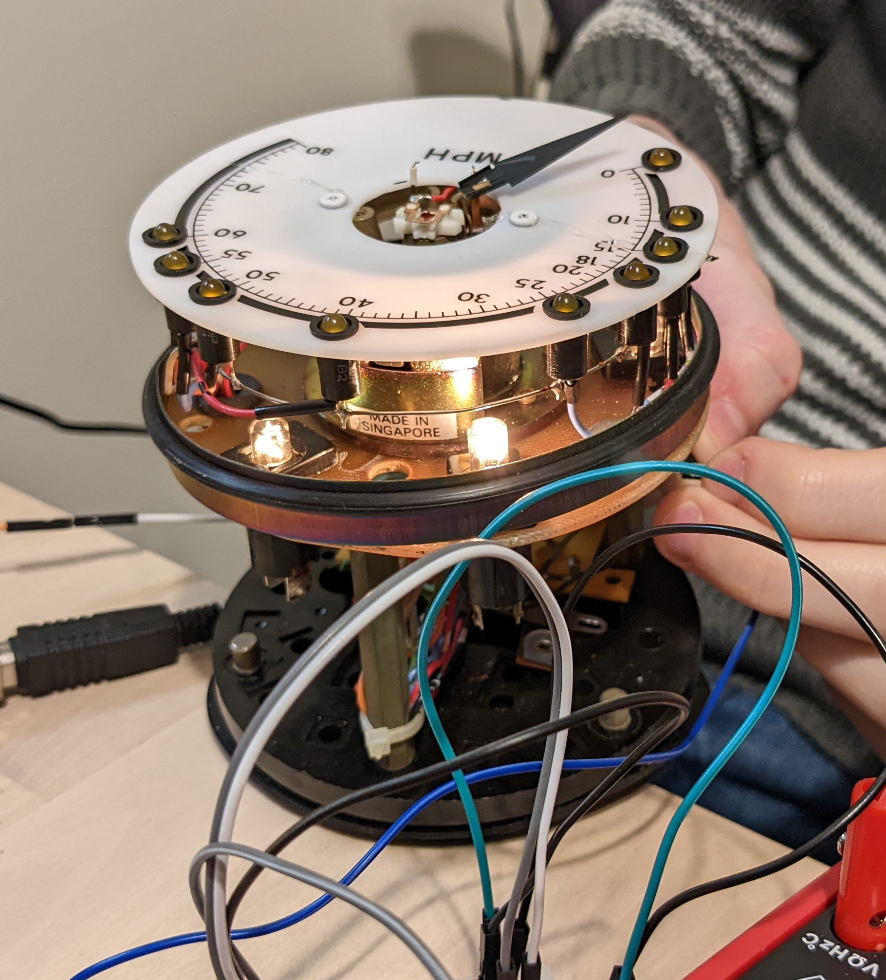
From the outside of the device, we can see a few notable things:
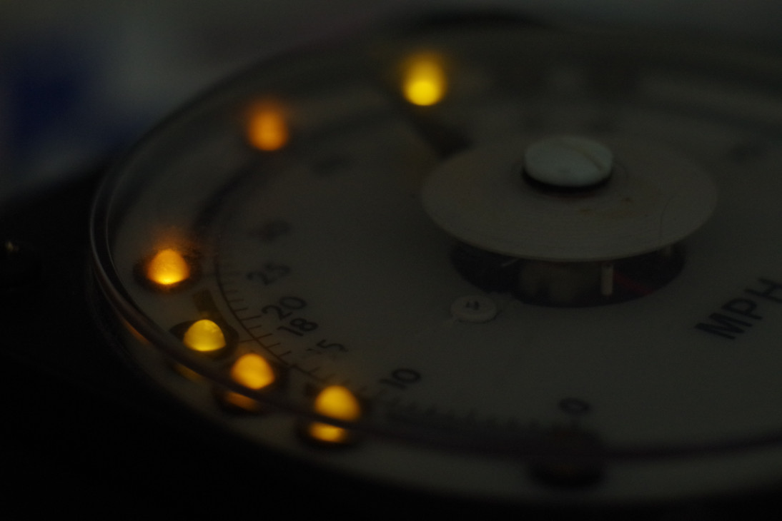
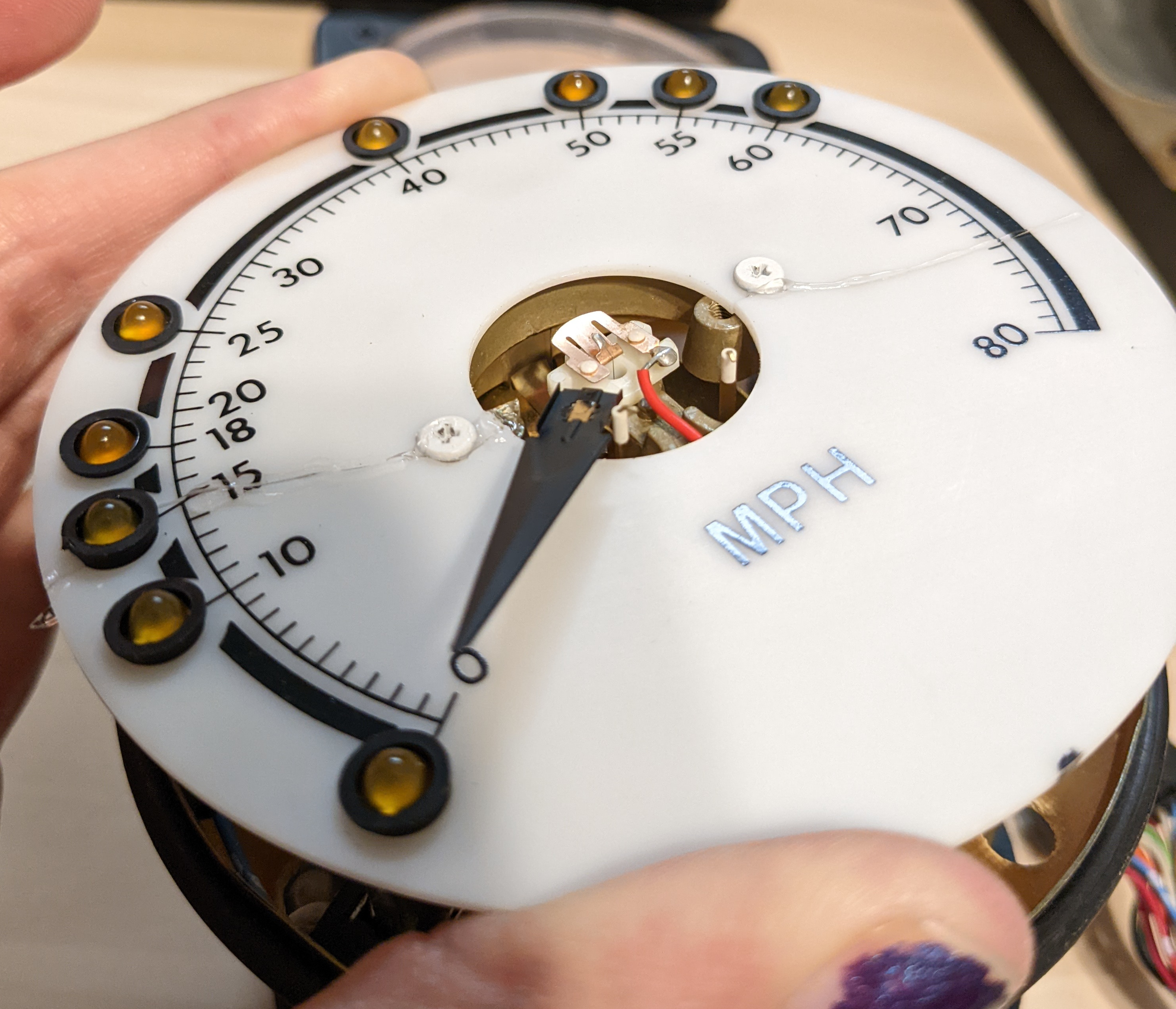
- A speedometer, with LEDs at certain specific points (0mph, 10mph, 18mph, 20mph, 25mph, 40mph, 50mph, 55mph, and 60mph)
- A big switch with “MAN” (presumably “Manual”) and “ATO” options (probably Automatic Train Operation as described)
- The serial number plate (not shown) indicates the manufacturer: “General Railway Signal”, who also made the ATO equipment on the Braintree branch!
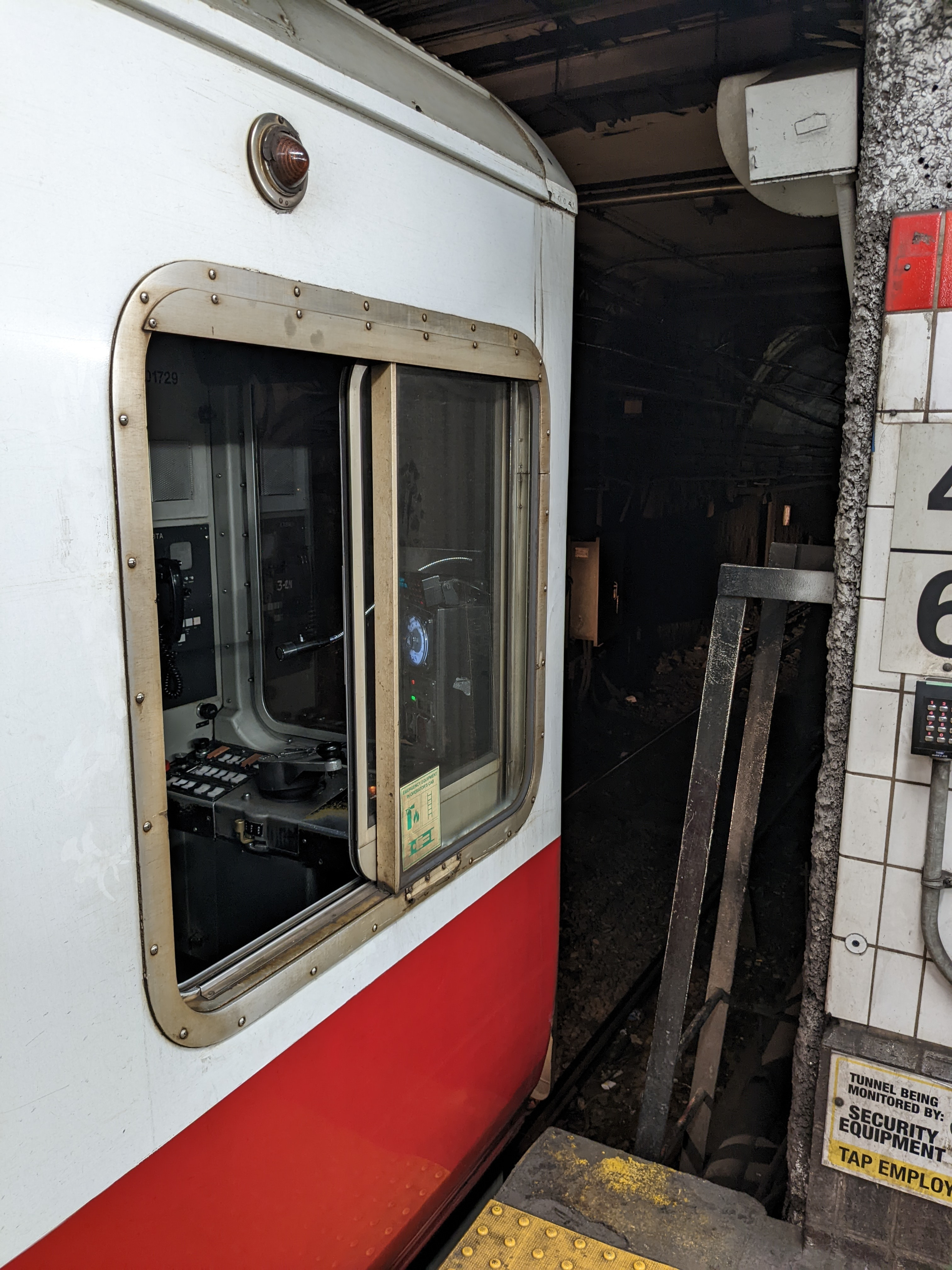
Additionally, looking at old Orange line Hawker cab footage, and peeking inside Red line cars today (pre-1800 series), we can see this device in the operator’s cab.
Given all of that, and knowing that the MBTA operates using ATO on the Red and Orange lines, we can guess that this is what a modern railway would call an aspect display unit – a device that allows the operator to see signal aspects (specifically speed limits) in the cab when a signal isn’t otherwise visible, and to understand and manipulate the state of the automatic train operation system.
Cracking it open
I plopped it down on the kitchen floor (it was too grimy for the table or carpet) and cleaned it off, wiping what must have been years of railroad and basement grime off it.
The front panel was held on with two strange screws I'd never seen before. I later learnedI figured this out by looking through McMaster-Carr’s website, since they sell every fastener in the known universe. It was fortunate that they were rather loose, as the appropriate screwdriver (MCM part #7309A22 for a No. 10 tri-groove screw) costs $20 for the bit alone. that these are tri-groove screws intended to be difficult to remove without the correct screwdriver, but I had no problem twisting them out with a pair of pliers. Whatever this device was, the MBTA clearly didn't want it messed with.
I lifted the front panel off, revealing a rat's nest of wires all plugged into a very basic circuit board. It was at this point that I realized I might be a bit out of my depth. It looked like there was a fair bit more going on here than just power to the lights and wires out from the switches and buttons, but it wasn’t complex enough to have any sort of processor or software.
We started our reverse engineering by trying to figure out which pins on the circular connector went where on the rectangular connectors. I held a multimeter probe on one pin of one of the rectangular connectors and watched the display (that meter didn’t beep when it detected continuity, unlike most other multimetersWhen we started on this project, the only multimeter either of us had was a very cheap one (I bought it for $5 at a hamfest) that was not particularly good at measuring anything. Its probes were too big to reliably poke a single pin, so I stripped some wires and twisted them around the ends, where they did not want to stay. Whenever we managed to electrically connect it to anything, it always took a long moment to read a resistance, during which we couldn’t tell if it was working or not.) while Tris poked each of the pins on the circular connector.
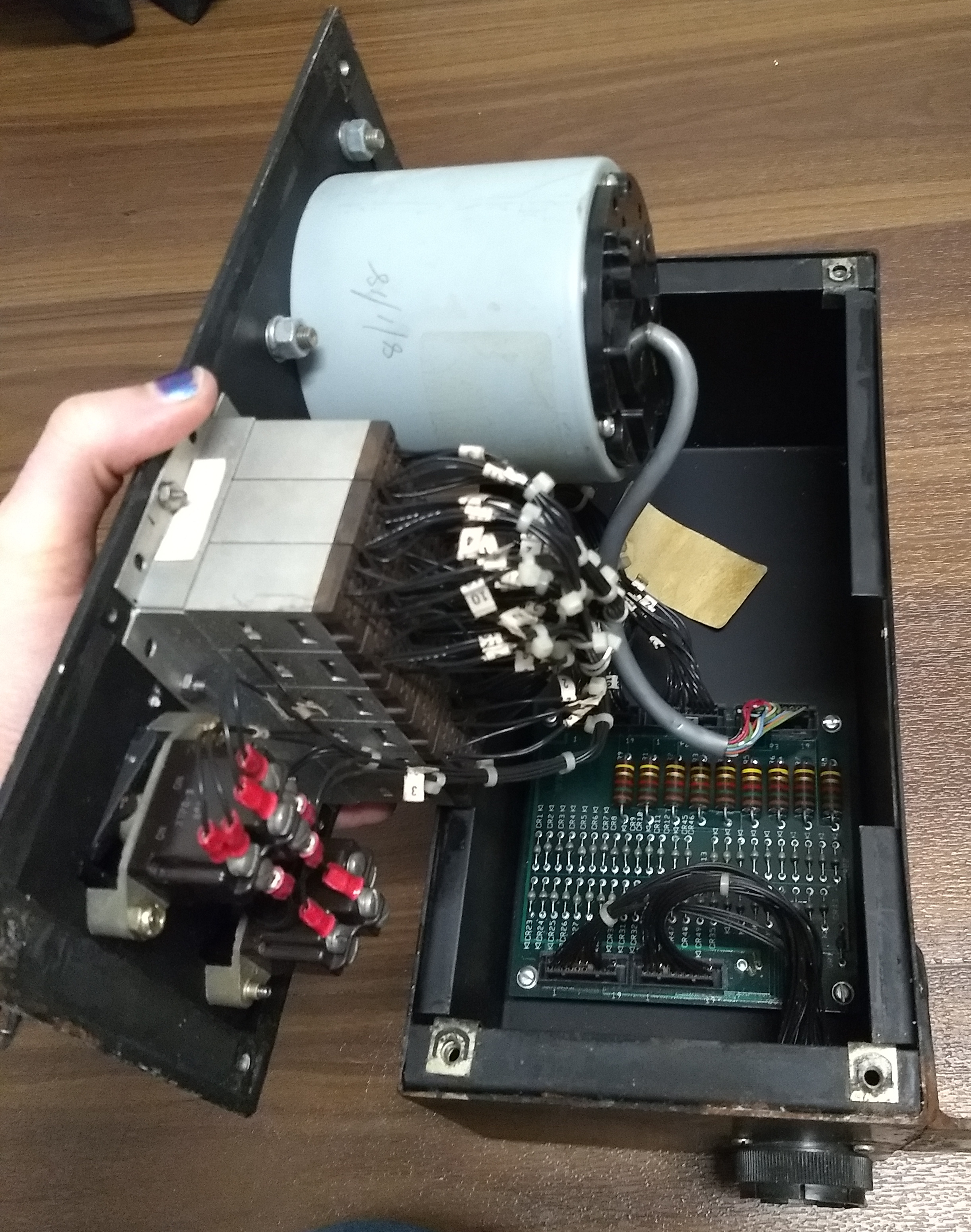
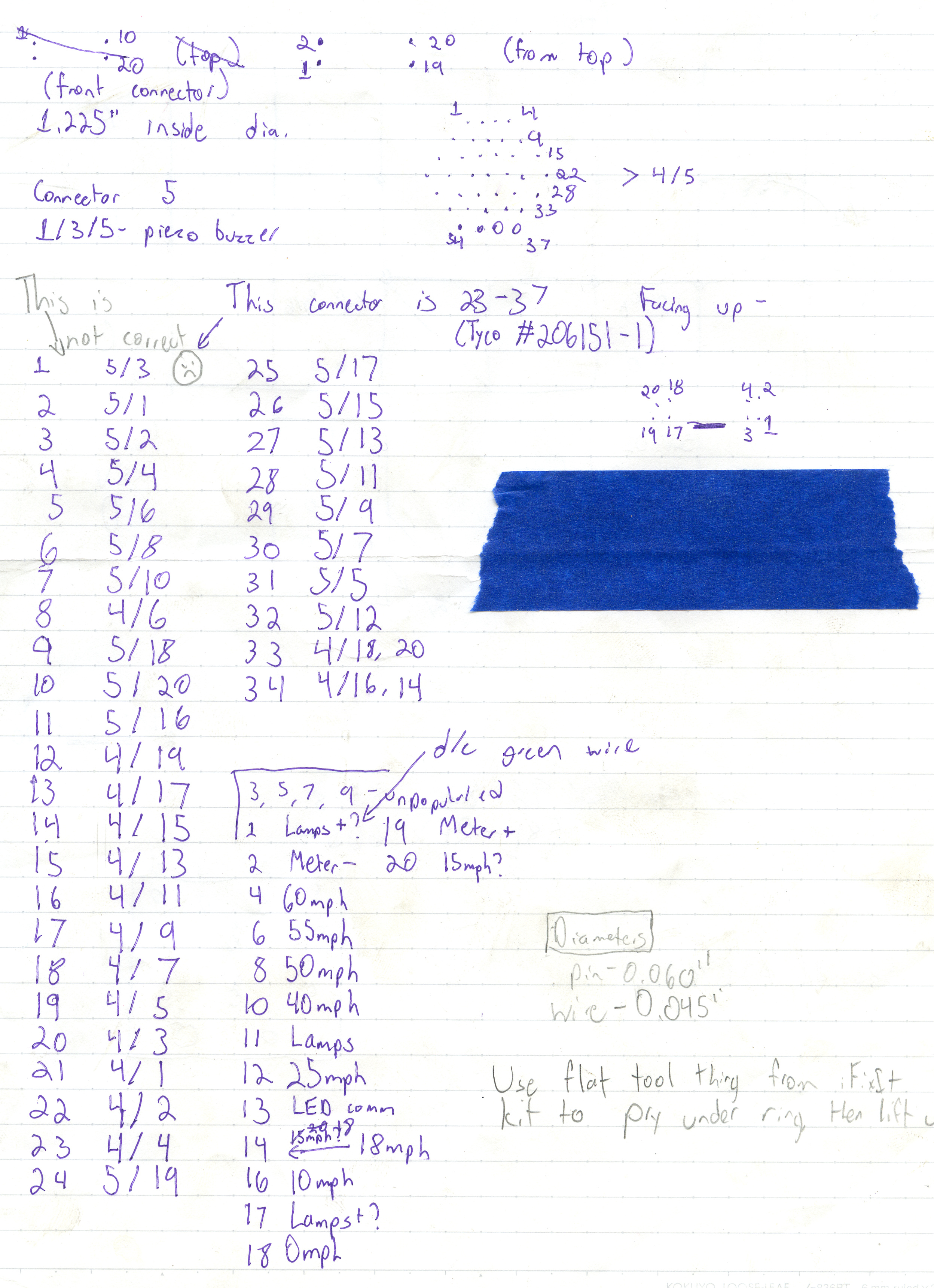
Once we knew where things went from the circular connector, we traced connections through the maze of diodes and resistors by picking a pin on one of the lower connectors and probing each pin on the upper connectors until we found it. Due to the conformal coating on the board, we could not simply trace paths using component legs.
I held the wires together as she pokes all the pins to no avail. She tries it again to make sure she didn’t miss anything – still nothing. We flip the multimeter probesthis worked because of the diodes! which we had not completely considered at the time and find it on nearly the last pin in the connector. “Do you know how hard it is to beep out a pinout when your reverse engineering partner is constantly flustering you?” I say before she leaned in for a kiss.
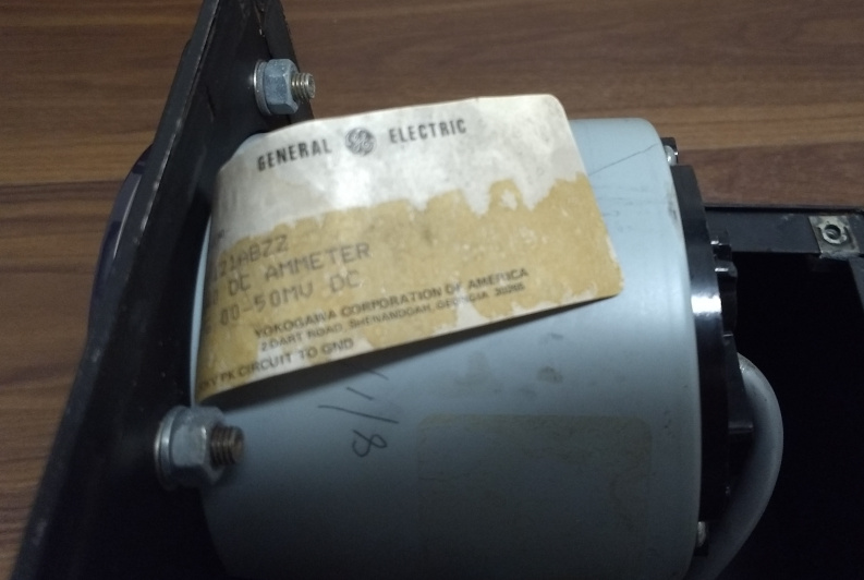
Once we had most of the board beeped out, we turned our attention to the speedometer, which proudly proclaimed itself to be a DC ammeter from General Electric. We unscrewed the screws on the back of it, and, to our confusion, nothing really moved. Even though the screws on the front seemed unrelated and only held the plastic dome on, we tried them too, and found that the entire speedometer assembly was intended to be pushed out from the back.
Inside, we found some wires with burn marks on the insulation, which we hoped weren’t connected to anything important (we would later figure out that they went to the incandescent bulbs and solder them back into place), and a delicate arrangement of LEDs on the speedometer dial. Tracing the LEDs back to the connector proved pretty easy once we remembered that they’re diodes, and left us with a couple pins that we traced to the incandescent bulbs and to the ammeter itself, although the polarity on them was uncertain.
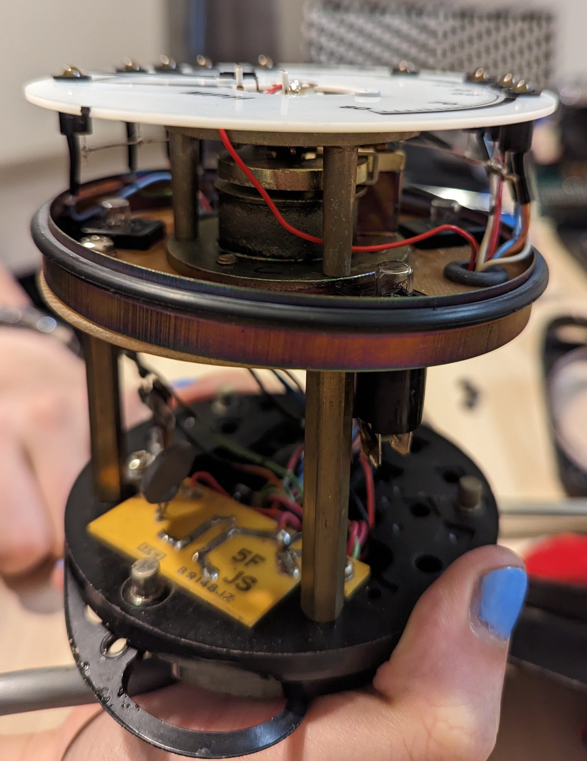
Getting the speedometer assembly back into its metal case proved to be even more difficult than getting it out. There is a metal ring around the outside of the assembly that had to be positioned just right to get it to seat back in the cylindrical case, and since it was only barely bigger than the speedometer dial, it was quite difficult to get back into place.
We pried at it with tools from my ifixit kit, and then Tris slipped and pushed the ring onto the dial of the speedometer, which immediately cracked in half. The broken dial pushed the needle of the ammeter off at an angle, and we agreed that this whole mess would be a problem for later.We glued the dial back together and bent the needle back months later, neither of us having gotten around to buying super glue or wanting to break it further.
Off-the-shelf parts
Much of this indicator was built from unmodified commercially-available parts, which made figuring out how it works a lot easier. We located a number of datasheets and attempted to align them with reality, some of which made more sense than others.
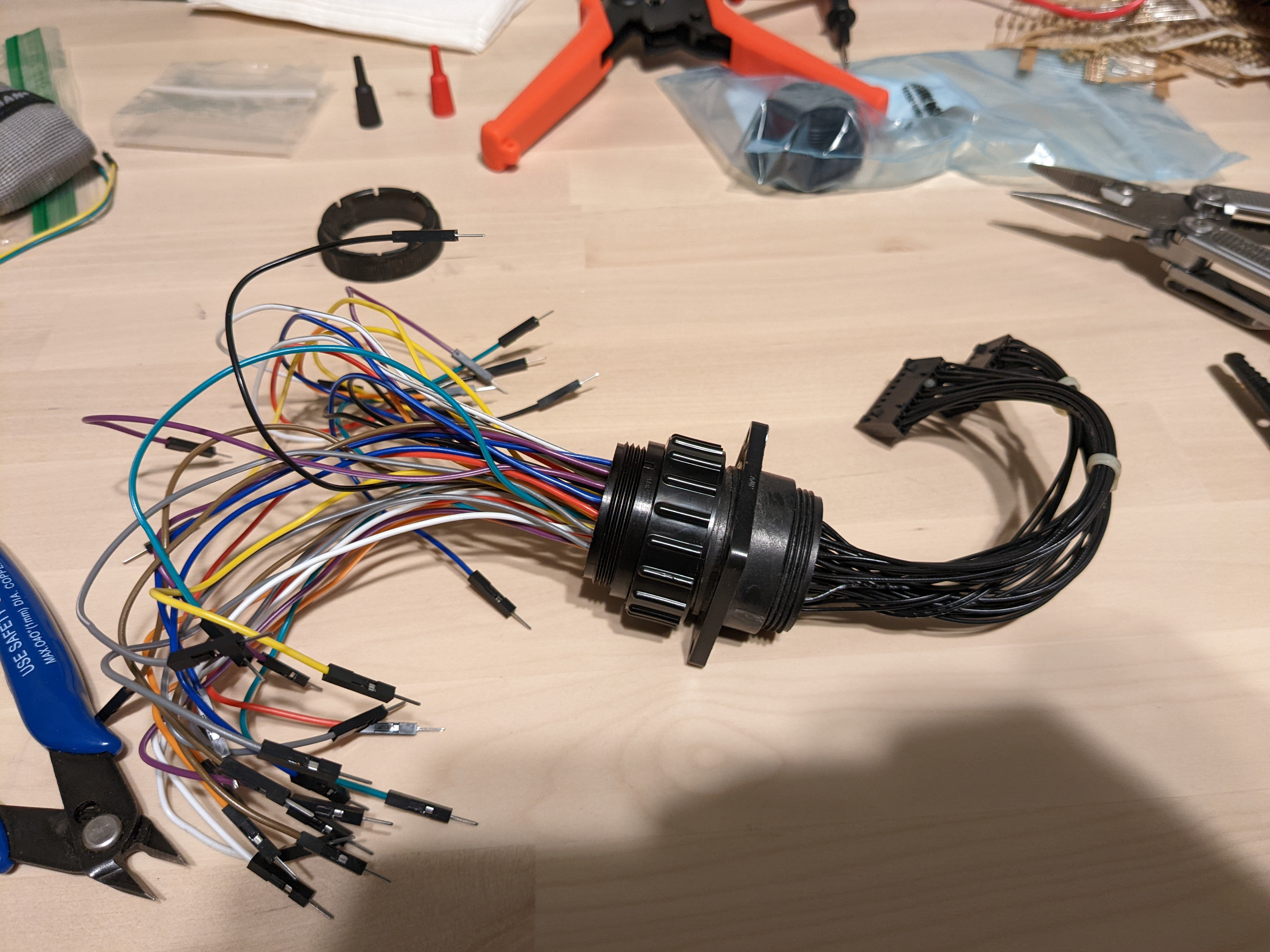
The circular connector
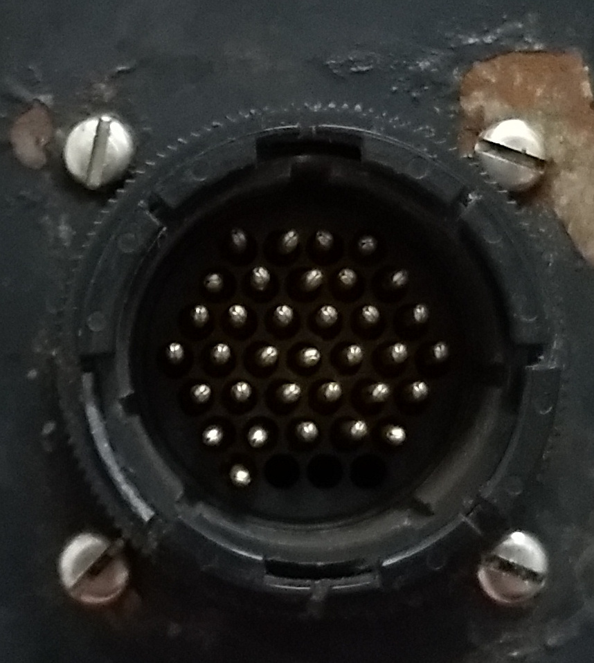
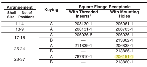
The circular connector is labeled with “AMP” on one side and “206151-1” on the other, which I initially overlooked (the markings are small). I tried googling the numbers and got a Digikey listing for this exact connector and a catalog that listed the part number for the plug that goes with it.
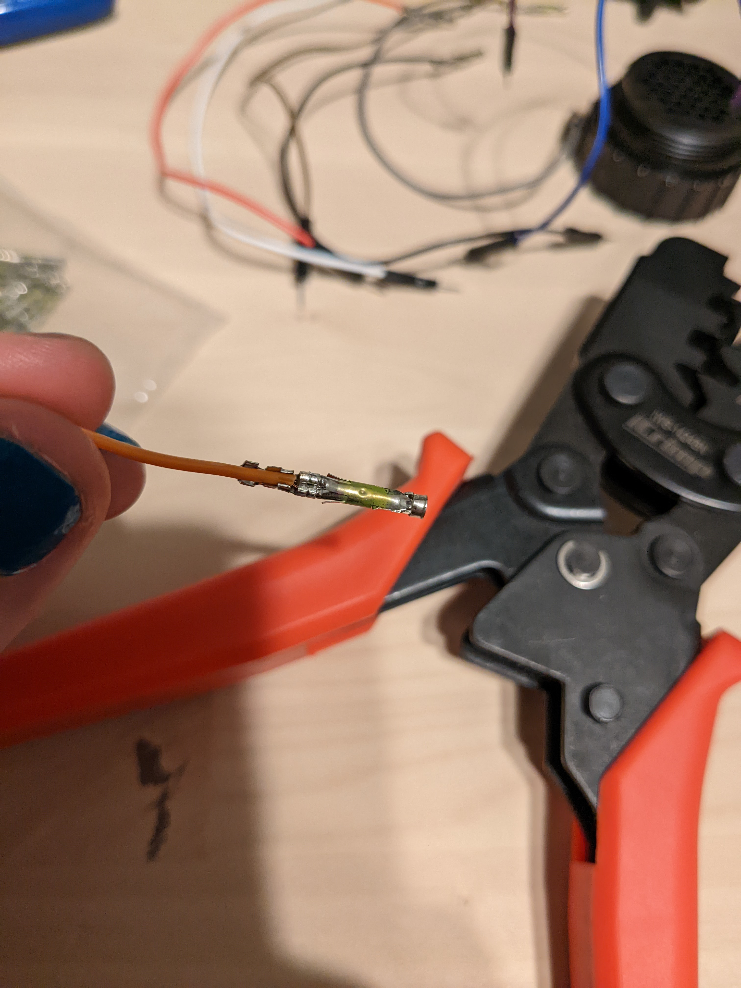
Finding the correct metal parts to put inside the plastic plug was a bit more difficult, as the meaning of “reverse gender” in the catalog was not exactly clear, and some of the listings on Digikey were more than $1 per ferrule, which seemed excessive. We eventually found what we needed at Mouser, although we passed on the $700(!) crimping tool they recommended; a much cheaper tool for a similarly-shaped automotive ferrule worked fine.

Building a wire harness for our connector
I strip the wire, twist it, slot the ferrule into the tool, insert the wire, and squeeze to crush the ferrule down onto the wire. The crimp tool’s ratchet softly clicks three or four times in my hand before hitting its end and releasing. I slide the crimped ferrule out and wiggle it a bit to make sure the wire is in there and set it aside to start on the next one. Once I’ve crimped all 34 of them, I bend the tabs at the back of the ferrule to hold onto the wire a bit better and slide it into the socket.
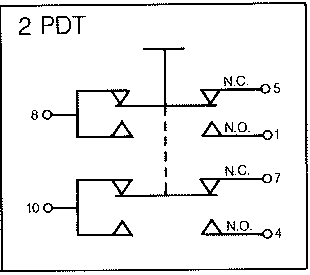
Lamps and buttons
The block of lights and buttons was marked with a sticker with three lines of text, none of which produced any useful results online when searched in their entirety. I tried searching just the first part of the first line and got some similar-looking switch assemblies, so maybe I was on the right track.
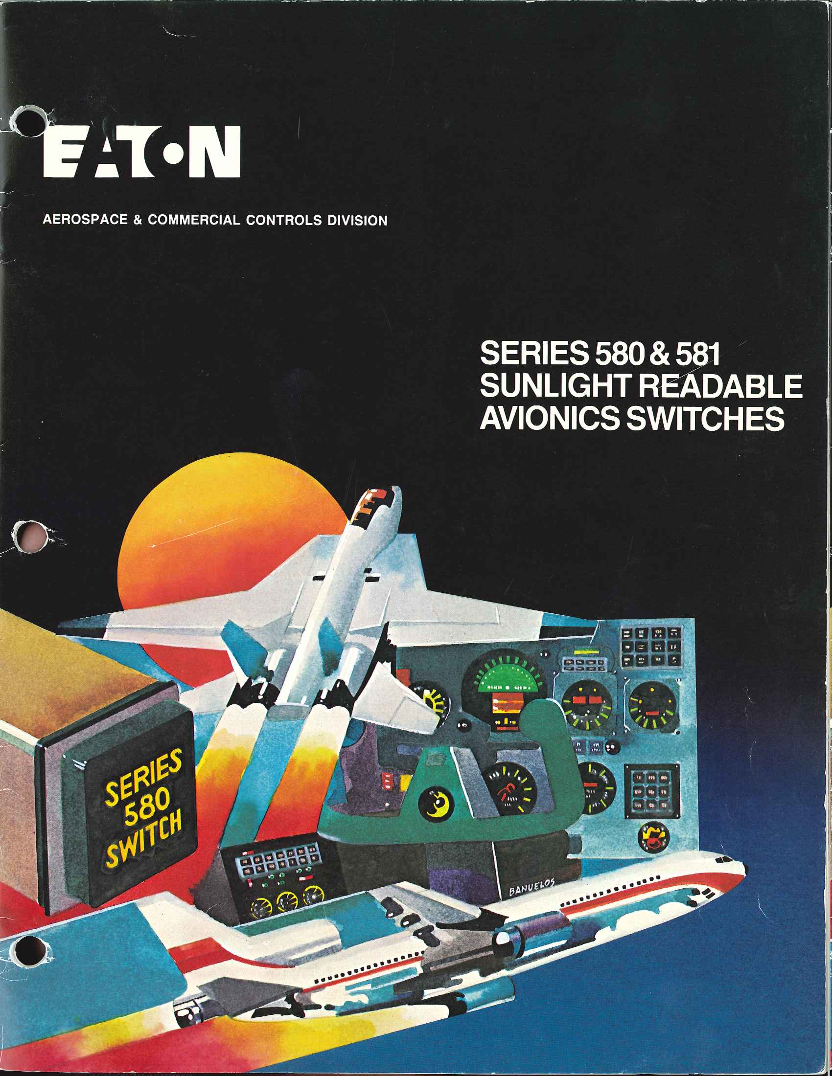
Changing up my searches with some of what I found eventually led me to this beautifully 80s catalog for Eaton’s 580 and 581 series of avionics switches, and the number 581 matched with the beginning of the second line of text.
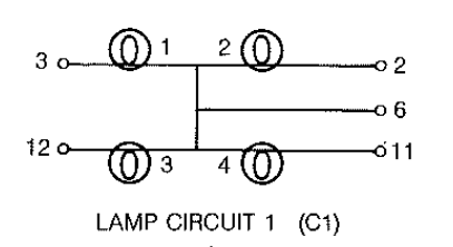
The line that started with 581 didn’t, however, match up with the part numbering scheme in the catalog. Based on the layout of wires on the switches and a bit of probing with the multimeter, we came up with a part number of 581 11 A2B7C1, meaning (in order) that it’s a series 581 switch, unsealed, with lamp circuit 1, and 2 pole double throw momentary with “matrix” connections.
The speedometer

The speedometer had a label on the side revealing that it was actually a DC ammeter made by Yokogawa and sold by General Electric, although I’m pretty sure that the speed dial and the LEDs were customWe had hoped that specifications for the LEDs would be included in the catalog listing for the ammeter, but they weren’t, and we ended up having to guess that they’d be the same as the incandescent bulbs.. I found the catalog pretty easily, but the exact part number on the ammeter in the indicator isn’t listed; it mentions specifying scale and other details, so I get the impression that this was a semi-custom job. The catalog did, however, reveal that this was a shunt-rated DC ammeter rated for 50 millivolts.
Shunt ammeters use a low-value resistor to divert a small fraction of a large current into the meter, and a given current shunt ammeter is usually calibrated for a particular value of shunt. Other ones in the catalog are calibrated for 0.050 ohms, but the line for this one says to tell the manufacturer your shunt value before ordering, and we were not the ones who ordered it. Here is a more detailed explanation of shunt ammeters.
Lights, camera, action!
I borrowed an adjustable bench power supply from my friend Jeff (thank you!), who has acquired a large quantity of test equipment from amateur radio operators in muddy fields (some of it even works!), and promised not to break or throw it in a river in frustration at the project. The catalog for the buttons listed several lamp voltages, so with some trepidation, we turned on the power supply to try them.
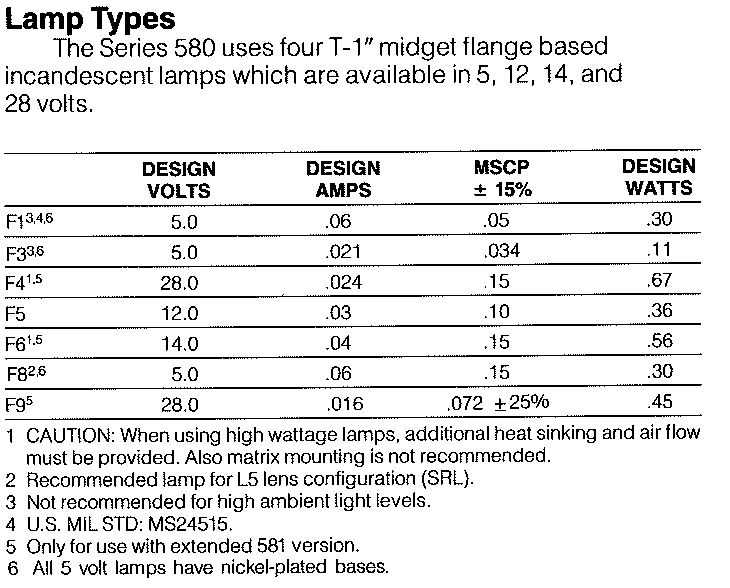
The supply made a series of rapid clicking noises as it switched from constant voltage to constant current and back. Tris patted it and it calmed down, and we turned up the voltage. At 5 volts, the first option listed in the catalog, we saw nothing whatsoever. She turned it up to 12 volts; still nothing. We try 14, even though 12 should be enough to get something out of that; still nothing. With even more trepidation, we turned it up to 20 volts and saw a faint glow, which gave us the confidence to turn it all the way up to 28.
Trying the same with the LEDs on the speedometer dial was the same process, but scarier. The LEDs appeared to be a custom installation, so we had no guarantees from a datasheet. We turned the power supply back down, wired it up through the resistors on the circuit board so it’d be harder for us to burn them out, and slowly ramped the voltage back up to find that the same 24-28V as the incandescent bulbs was fine.
We later switched to a 24 volt power supply originally intended for some variety of MikroTik device, which still requires some headpats, but not as many as the bench power supply. To use it, we got a suitable barrel jack from "You-Do-It" Electronics, a nearly cubic building in the shadow of broadcasting towers in Needham. We ended up going there several more times to get the parts we needed while we still had the motivation to use them rather than waiting for shipping.
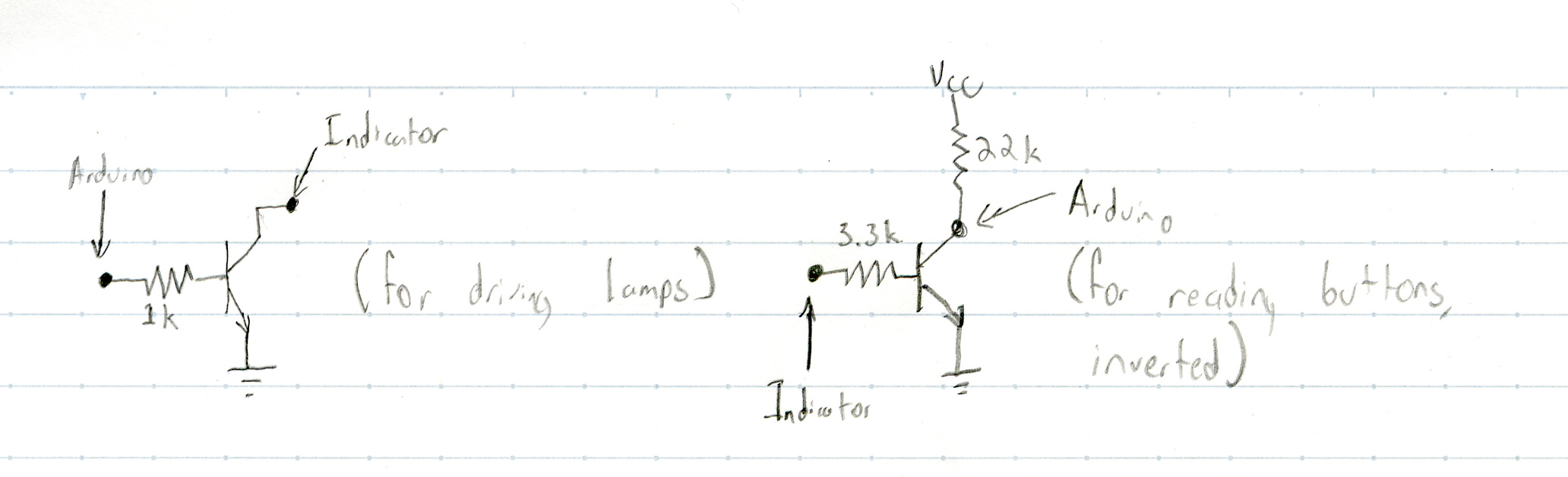
Driving the indicator from a microcontroller
In order to do anything interesting with the hardware, we’d need to drive the 28V components (and the ammeter) from a lower-voltage board (in our case, an Arduino microcontroller). With the help of Horowitz and Hill (and their textbook The Art of Electronics), we designed a transistor switch circuit and tiled it a few times to make this work.
Since our microcontroller didn't have enough I/O pins to drive every transistor directly, we used two SX1509 breakout boards from SparkFun instead. These were very easy to put together (through-hole soldering) only, and SparkFun's Arduino library was well-documented.
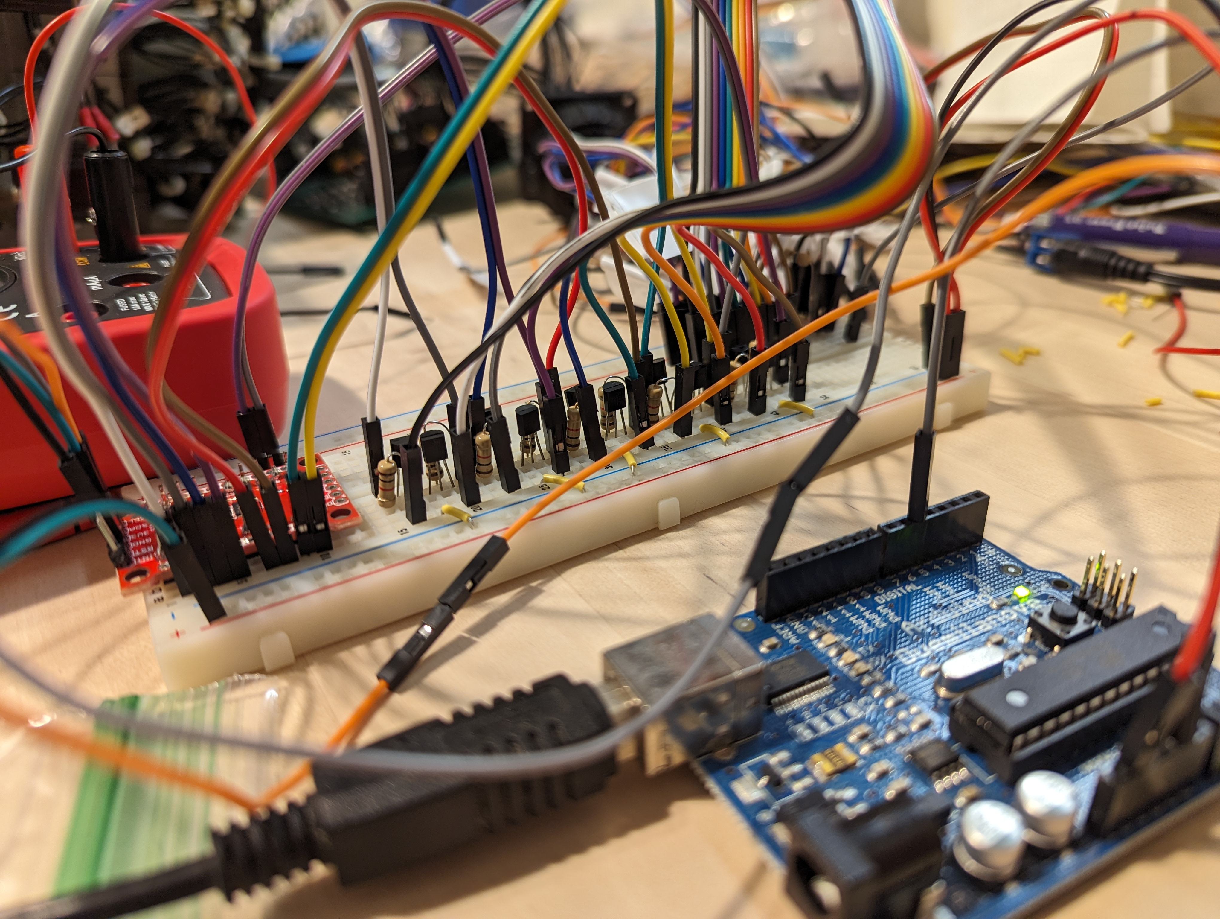
After verifying that the transistor switch idea worked reliably, we built the rest of the switch circuits on the other side of the breadboard, mirroring what we had done here. We had trouble getting the lamps connected to that side of the board working though — at this point it was pretty late in the day, so we decided that it was a problem for tomorrow.
As we fell asleep together, Tris suddenly said “the transistors are backwards.” I reply with a confused noise, halfway asleep. “The transistors are backwards,” she says again and writes a note to herself on her phone. This project has had a way of haunting our dreams.
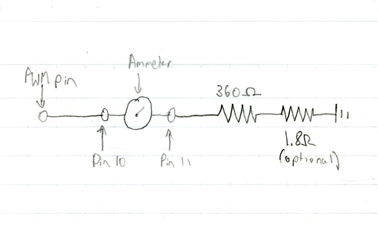
After fixing the transistors the next morning, we moved on to figuring out how to drive the ammeter. It's nominally rated for 50mV at 50mA, so we were a bit afraid to push it any farther, but after some experimentation we found that driving it using PWM from an Arduino pin (configured as an analog output) in series with a 360 ohm resistor worked fine. We had to build a mapping of analogWrite() values to speedometer values, but that was relatively straightforward.
I wrote most of the Arduino program to drive the lights and meter, copying a fair bit from SparkFun’s example code for the I/O expanders. Remembering problems that took forever to debug back when I was on a FIRST Robotics team in high school, I made sure to put the pin numbers for everything in one central place at the start of the file.
The first version of the program just turned on some lights to make sure that they worked, but I soon changed it to wait for input over serial with which pin number to turn on. We also calibrated the speedometer, noting down what the needle pointed at at each given PWM value and producing a lookup table to put into the Arduino code.
Once we had that mostly working, Tris sketched out a protocol more suited to controlling it from a program, with one byte for a command (+ for on, - for off, / to set the speedometerbecause it looks like a speedometer needle lol, ! for a lamp test, ? to query the state of an input pin, and = to read the state of an output pin), one byte for a value (which pin to read or write or what to set the speedometer to), and then a newline character. I implemented it on the Arduino and in a Python script that replicated the previous behavior of prompting for a pin number, but now in a way that can easily be controlled programmatically.
Connecting the indicator to a car
Our friend Ava casually suggested that we use the indicator as a speedometer in my car, and that nerdsnipedSee XKCD 356. us into trying to make it work. “It can’t be too hard, right?” was our refrain through that weekend of programming and putting it all together.
I messaged our friend Hunter (thank you!) because they’d messed around with car electronics and OBD2 before, and they suggested I get a cheap Bluetooth ELM327 adapter that cost about $5 shipped. The next weekend, the adapter arrived and I plugged it into my car’s diagnostic port under the steering wheel, and Tris eagerly tried to connect to it while I drove to our favorite local deli.
Convincing her NixOS thinkpad to talk to it proved easier said than done, and we even tried using my Windows thinkpad in hopes that would work. Concerned that I had bought some ewaste masquerading as a OBD2 interface, she installed an app on her phone to connect to it, which did work. After much futzing around with NixOS and a journey through the strange realm of Bluetooth serial, she got it to read values, and neither of us had ever been happier to see something read zero.
Tris sat down on the sofa with her laptop muttering something about a grid of overlapping squaresshe later discovered that the squares did not actually need to overlap, and several hours later she had written a mountain of code to find the nearest thing OpenStreetMap thinks is a road from a given slice of location historyThis problem surprisingly doesn't have a readily available solution that we could drop in to this project; at least not one that can handle real-time data like we are generating.. From that, she could find the speed limit (not tagged on most nearby roads) and then send it to the indicator.
While she rotated squares in her laptop, I worked on Python code to send commands to the indicator and made it a fair bit less sketchy and not require constant looking at the Arduino code to be sure I’m using it right.
In the passenger seat of my car, Tris surrounded herself with the nest of wires needed to power and control the indicator. First, she plugged in the rather temperamental inverter and gave it a few headpats before connecting it to the socket hanging out of the cookie box. Next, she balanced the indicator itself between her and the center console and plugged in the large circular connector. Her laptop came next, balanced precariously and connected over USB to the Arduino hidden in the nest of wires. I started the car and plugged in the OBD2 adapter, which lit up bright blue, and she connected to it from the laptop. After turning up the OwnTracks update frequency, everything was ready to go, and we waited hopefully for the program to load its map data and talk to the indicator.
I drove to the highway, since almost none of the streets in my town have speed limits tagged in OSM, and, to our surprise, it seemed to mostly work, although it quickly broke. With a push of the lamp test button, Tris confirmed that the problem was with power, and she got out the multimeter at fifty-five miles per hour. The inverter was not reliably getting power through its somewhat corroded cigarette lighter plug, so we headed home, not really able to do much more on the road.
I disassembled the inverter’s plug and soaked the pieces in vinegar, which removed some of the corrosion, and scrubbed them with aluminium foil, which removed even more of the corrosion. After washing the parts in isopropyl alcohol and reassembling them, the inverter became somewhat less temperamental, although it still needed headpats and plenty of wiggling the plug to make it work properly.
With a few more software tweaks and another test run on the highway, we were confident that this Rube Goldberg machine worked well enough to film and show off, which we made plans to do the next weekend.
We published a diagram of this whole system on GitHub.
Putting it all together
Tris put on her witch hat and we headed out to meet up with our friend Maxine (thank you!) at Alewife on a cloudy Sunday afternoon. Hopes were high, as we’d tested everything except for the “YARD 10” codethe intent here was to light the "YARD 10" lamp as long as we were still in a parking structure the previous weekend, but our hopes soon turned to frustration.
I patted the inverter while Tris wiggled the plug until it gave a soft beep. She checked the voltage, holding the barrel hack and one multimeter probe in one hand, and it read a bit below 24 volts. “This is the witchiest thing I’ve ever seen, and I know actual witches.” said Maxine from the seat behind me. Tris pushed the lamp test button and the lamps came on, so we knew it was getting power. She ran the program again and we sat, waiting for it to parse the map data and turn on the “YARD 10” light. Thirty long seconds later, it finished parsing and attempted to communicate with the indicator, but the lights only turned on briefly and back off.
“What’s your favorite 8 bit value?” she asked, and I answered with “42”, leaving it ambiguous whether I meant that in decimal or hex. She used this to add a “handshaking” feature to ensure that the computer was sending commands when the Arduino was expecting them, but this did not make the communication any more reliable. It was at this point that we realized that we had been sitting in a car for a while and that none of us had eaten lunch yet.
After a break for burritos in Davis Square, we returned to the car, where handshaking still didn’t work, so Tris undid that change. After another quarter-hour of troubleshooting, I suggested rebooting the Arduino, as I’d done that after every time I loaded code while testing earlier, and to both of our surprise, it worked.
This was when we discovered that the laptop wasn’t talking with the OBD2 adapter and my car. Instead of trying to solve this problem in a normal way, Tris immediately started writing code to use the GPS position history to estimate speed. “Quick, how many meters are in a mile?” she asked and I quickly searched it on my phone.
We had to be moving to test the GPS speedometer, and almost as soon as I pulled out of the garage, it started reading extremely high values and proceeded to crash after trying to tell the indicator we were moving 300 miles per hourRecall that our protocol definition specifies all values as bytes; sending a value faster than 255mph isn't well-defined.. While I drove us back to the garage, Tris started writing what she thought would fix this. I parked, she restarted the code, and we ventured forth again, only to get similarly ridiculous values.
Since the OBD2 adapter had worked the previous week, we tried it again. The laptop seemed to be connecting to it, but not getting any data back, but it had always been a bit finnicky. Tris tried connecting to it with her phone, which we’d used earlier to make sure I hadn’t bought literal ewaste, and it retrieved values from the car, so we knew that it still worked. She reconnected the adapter to her computer and it reported zero miles an hour, as it was supposed to. We made sure everything else was set up properly and asked Maxine to start filming.
I pulled out of the garage, a bit nervous that the indicator could stop working at any moment and trying to drive as smoothly as possible. The wait at the stoplights in the Rte 2/Rte 16/US-3 intersection dragged on seemingly forever, but the lights finally went green and I accelerated the car forward. The speed limit lights come on on the indicator as the intersection becomes a highway, Tris’ code locking onto what road we were on. As I took the second exit and Maxine stopped filming, I breathed a sigh of relief.
Thanks for reading. If you have questions or comments, or want to share more information about automatic train operation at the T, you can reach Tris via email at tris@tris.fyi.